
Home \ Blog \ Sub Bottom Profiling Survey in UAE: Seeing Beneath the Seabed
Sub Bottom Profiling Survey in UAE: Seeing Beneath the Seabed
September 9, 2026
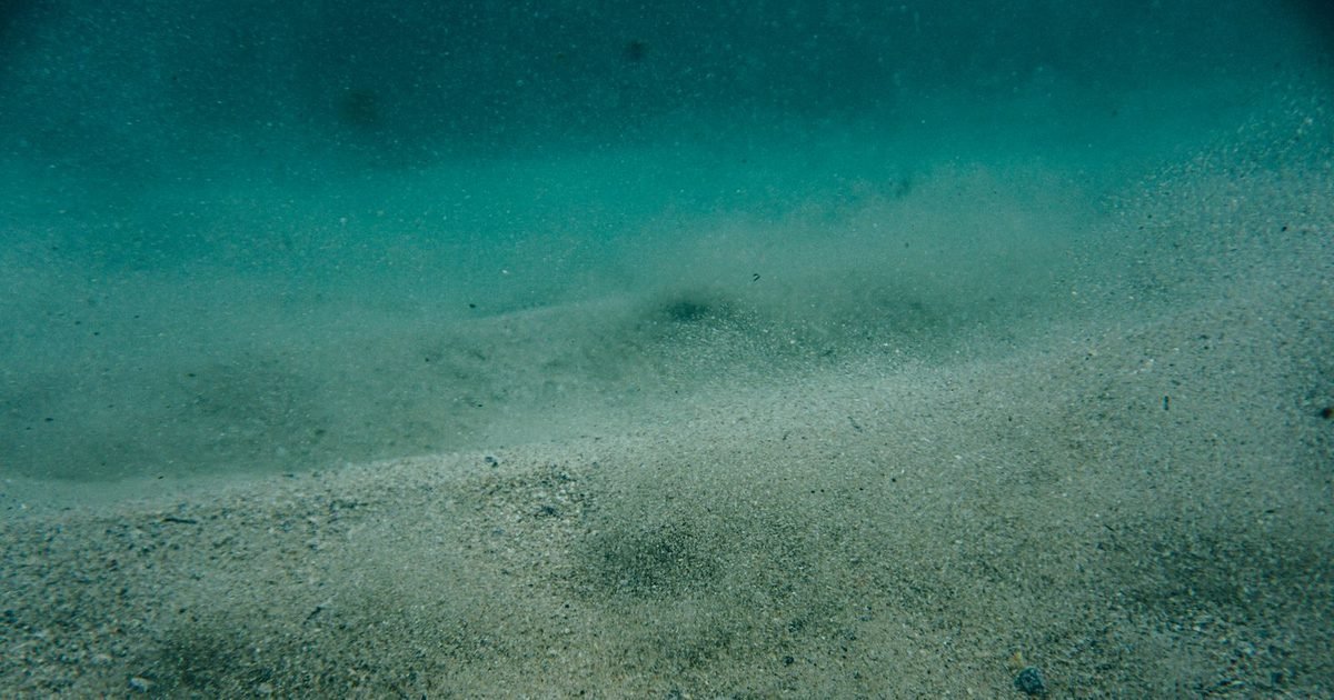
Bathymetry tells you where the seabed is. It says nothing about what lies underneath it. A Global Map Survey’s sub-bottom profiling and magnetometer surveys page fills that gap, imaging the sediment layers below the bed so that dredging, piling and cable burial can be planned against real ground rather than an assumption. This article explains how the method works, which acoustic source suits which Gulf ground condition, what the results look like, and the decisions that change once you can see the layer boundaries instead of guessing at them.
Key Takeaways
- Sub bottom profiling images layers below the seabed acoustically. It shows where soft sediment ends and stiffer material begins, along a continuous line rather than at isolated boreholes.
- Source choice is the whole decision. Higher frequency gives thin layer detail and shallow penetration. Lower frequency reaches deeper but blurs the fine structure.
- Geophysics and geotechnics work together. Profiles give continuity between boreholes, and boreholes give the profiles their ground truth.
How the Method Works
A sub bottom profiler sends an acoustic pulse into the seabed and records the energy that reflects back from boundaries where the acoustic properties of the material change. A soft mud over dense sand contact reflects strongly. Two similar sands do not. What comes back is a vertical section along the vessel track, layer boundaries stacked beneath the seabed return.
The principle is the same one used in reflection seismology on land and in deep water, scaled down for shallow penetration and high resolution. Because the vessel moves continuously, the output is a profile rather than a point, and that continuity is exactly what a borehole programme cannot give on its own.
Two limits govern everything. Penetration falls as frequency rises, and resolution falls as frequency drops. You cannot have both from a single source, which is why a survey looking for thin layering near the bed and a survey looking for rockhead at depth are different jobs even on the same site.
Gas is the other constraint that matters in the Gulf. Shallow biogenic gas in organic rich muds scatters acoustic energy and produces a blanking zone beneath which nothing is imaged. That is not a fault in the survey. It is information, and a competent report says so rather than presenting a blank as an absence of structure.
Matching the Source to the Ground
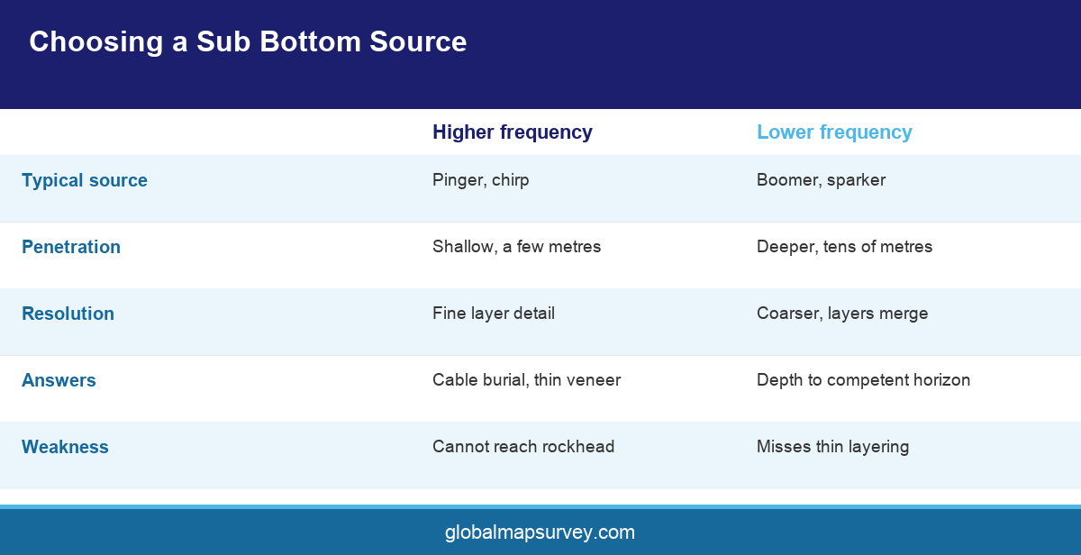
A pinger operates at the high end and resolves layering in the top few metres with fine detail. It is the right tool for cable burial assessment, thin veneer mapping and shallow archaeology, and it is the wrong tool for finding rockhead under twenty metres of sand.
A chirp source sweeps a frequency band and processes the return, which buys both better penetration and cleaner resolution than a single frequency pinger of similar power. Chirp systems have become the default for nearshore work across the region because they cope well with the layered sand and carbonate sequences common along the Gulf coast.
Boomer and sparker sources sit at the low frequency end. They penetrate tens of metres and are used where the question is depth to a competent horizon rather than the structure of the top metre. The trade is obvious in the record. Layers that a chirp would separate cleanly appear as a single thicker package.
Most well specified marine geophysical campaigns in the Emirates run more than one source on the same lines, precisely so that the shallow detail and the deeper structure are both captured. Doing that on a single mobilisation is far cheaper than returning because the first survey answered only half the question.
Local ground conditions push the selection in a particular direction along the Gulf coast. The shallow sequence is dominated by carbonate sands, cemented caprock and layered sabkha deposits, and the acoustic contrast between a loose sand and the cemented material beneath it is usually strong enough to image cleanly. What defeats a survey here is less often weak contrast than shallow water itself. In a few metres of water the seabed return and its first multiple arrive close together, and a source with a long pulse simply cannot separate them. Short pulse chirp systems and careful processing are what recover the top metres in those conditions.
What the Results Change
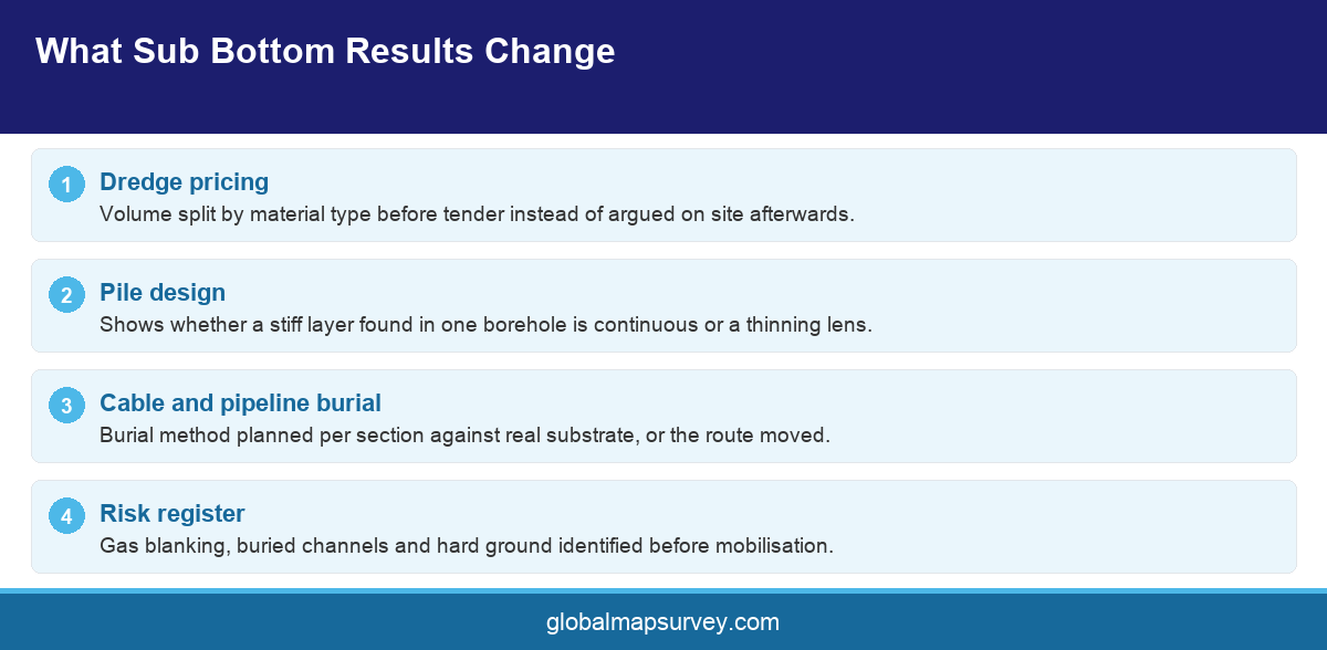
Dredging is the clearest case. A dredge priced on the assumption of soft material that meets cemented sand or caprock halfway through becomes a claim. Profiles that map the top of the hard layer across the footprint let the volume be split by material type before anyone prices it, which moves the argument from the site to the tender.
Foundations are the second. Pile driveability depends on what the pile passes through and what it stops in. A continuous section between boreholes shows whether a stiff layer identified in one borehole is continuous across the structure or is a lens that thins out, and that distinction changes both the design and the installation method.
Cable and pipeline burial is the third. Burial tools have limits, and knowing where the substrate changes along a route lets the burial method be planned per section rather than assumed uniform. The same data supports a route optimisation exercise that can shorten the length or avoid the difficult ground altogether.
There is a fourth case that owners forget until it stops them. Marine archaeology and buried obstruction risk both sit in the shallow section, and both are cheaper to find in a survey record than in a dredge bucket. A buried channel filled with soft material, an abandoned pipeline, a discarded mooring block or a wreck partly covered by sediment will all appear on a good sub bottom record long before anyone excavates. Discovering one during construction stops work while it is assessed, and on a project with an environmental consent that stoppage can run for weeks.
Across all three, the sub bottom record should be read alongside seabed sampling and borehole logs. Geophysics gives continuity and geotechnics gives identity, and a report that ties the two together is more useful than either alone.
Specifying and Reading the Survey
Ask for the target penetration and the target resolution as separate numbers, because they drive source selection independently. Ask for line spacing and orientation to be justified against the geology you expect rather than set by habit. Where a structure footprint is involved, tie lines running perpendicular to the main pattern are what let the interpreter build a coherent layer model rather than a set of unconnected sections.
Water depth also sets a practical minimum on what the survey can do, so agree early whether any part of the area is too shallow to work safely and how that ground will be covered instead. A nearshore strip that a survey vessel cannot reach is often better handled from a shallow draught boat on a separate mobilisation than left as a gap on the drawing.
Insist that the interpretation is delivered separately from the data. A processed seismic section is a picture, and the value lies in the horizons an interpreter has picked on it, with their confidence stated. Horizons picked with no borehole control should be labelled as such.
Finally, agree how the results will be handed over. Interpreted horizon surfaces in a format your design team can load, alongside the sections themselves and the processed navigation and positioning data, make the survey reusable. A folder of images does not.
Conclusion
A sub bottom profiling survey in UAE turns the seabed from a surface into a section. It shows where soft material ends, whether a stiff layer is continuous, and where gas or hard ground will interrupt a dredge or a pile. Specify penetration and resolution as separate requirements, run more than one source where the question spans both, and tie the interpretation to borehole control before anyone designs against it. To plan a marine geophysical campaign in Abu Dhabi or the wider Gulf, speak to the Global Maps Survey marine team.
AN ISO 9001-2015 CERTIFIED COMPANY