
Home \ Blog \ Deformation Monitoring Survey in UAE: Accuracy and Reporting
Deformation Monitoring Survey in UAE: Accuracy and Reporting
August 20, 2026
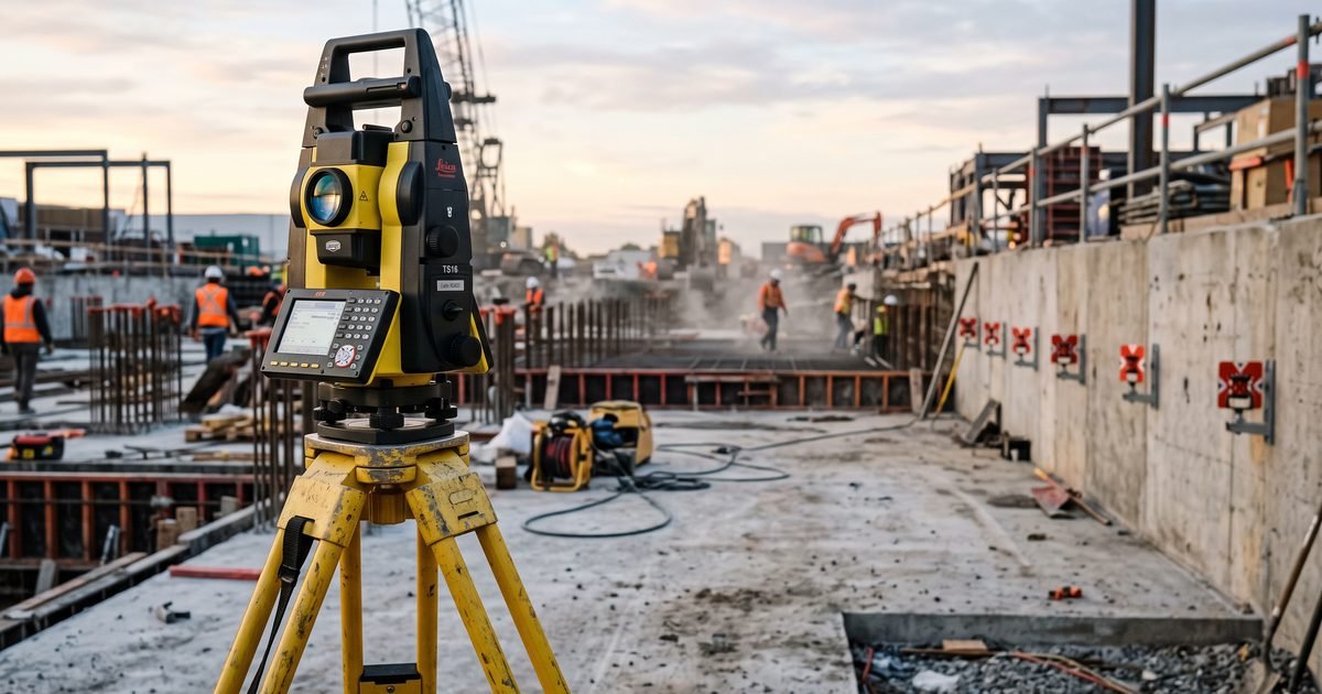
A deformation monitoring survey in UAE is commissioned to answer one question: is this structure moving, and if so, how much and in what direction. The difficulty is that the movements that matter are often smaller than the errors an ordinary survey setup will produce. This guide explains how instruments are matched to the movement being tracked, how accuracy is specified properly, and what separates a monitoring report that gets used from one that gets filed.
Key Takeaways
- Accuracy must be specified as a number the survey can be held to, and it must be finer than the smallest movement you need to detect.
- Instrument choice follows the movement. Vertical settlement, lateral displacement and tilt are not all best measured the same way.
- A monitoring survey with no stable reference network is measuring the reference points as much as the structure.
What Deformation Monitoring Actually Measures
Deformation monitoring covers any change in the position or shape of a structure over time. That includes vertical settlement, horizontal displacement, rotation, tilt, convergence across an opening and bending along a member. Each of these behaves differently and each rewards a different measurement approach.
Confusing them is a common source of wasted budget. A programme specified as settlement monitoring will not detect a wall leaning outward, because levelling only reports height. If the risk is lateral movement of a retained excavation, the programme has to be designed to measure position in three dimensions rather than height alone.
The first conversation should therefore be about failure mode, not instruments. Once you know how the structure is expected to move if something goes wrong, the measurement method follows almost automatically. Our deformation monitoring work usually begins with that discussion.
It is worth agreeing early what will not be measured. Monitoring scopes tend to grow, and a programme trying to capture every possible movement mode across every element becomes expensive without becoming more useful. Naming the movements that matter, and stating explicitly which ones are accepted as out of scope, keeps the design focused and gives everyone a clear record of what the data can and cannot answer.
Matching the Instrument to the Movement
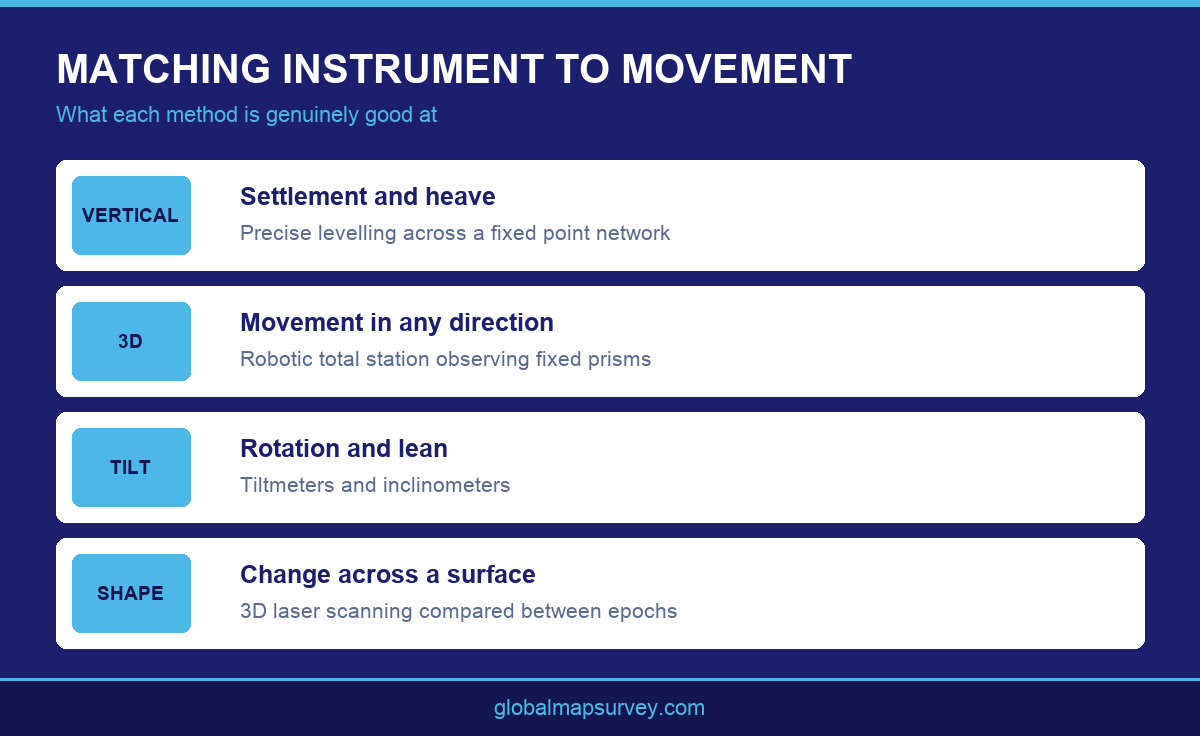
Precise levelling remains the most accurate way to track vertical movement and is still the default for settlement work. It is slow, it needs line of sight, and it says nothing about horizontal position, but for pure height change over a network of points it is difficult to beat.
A total station measures position in three dimensions and suits structures where movement could occur in any direction. Robotic versions can be left in place to observe prism targets repeatedly without an operator, which makes them the usual basis for continuous schemes. Tiltmeters and inclinometers handle rotation and subsurface lateral movement, neither of which a total station sees well.
Where the concern is change in shape across a whole surface rather than movement of discrete points, 3D laser scanning captures dense coverage that can be compared between epochs. It is less precise per point than levelling, so it complements a point based network rather than replacing it.
Combining methods is common and usually sensible. A scheme might use levelling on a network of settlement points, a robotic total station on prisms fixed to a retained wall, and tiltmeters on a small number of critical elements. Each covers a different failure mode, and the combined picture is far stronger than any single method stretched beyond what it does well. Settlement points established for building settlement monitoring often form the vertical backbone of that arrangement.
Specifying Accuracy So It Means Something
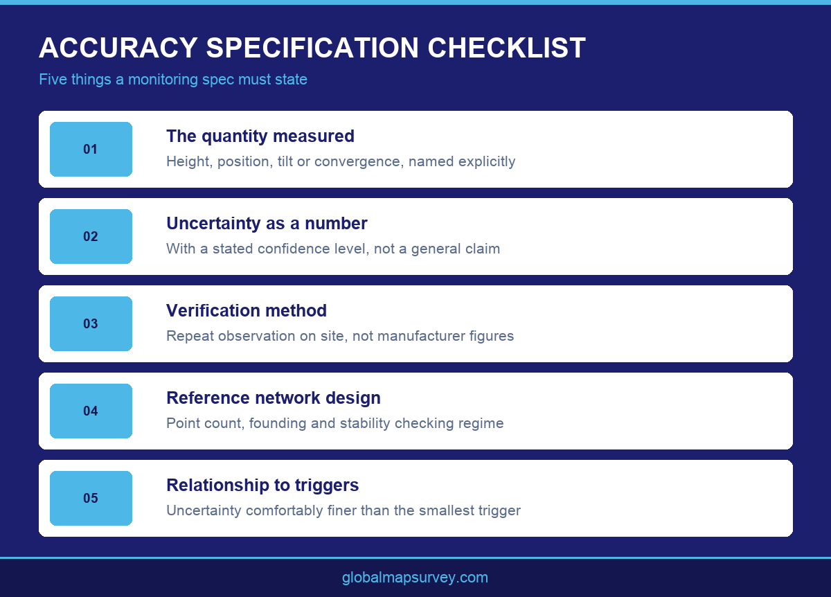
Accuracy in a monitoring specification has to be a stated value with a stated confidence, applied to the quantity you care about. A general claim that the survey is precise tells a contractor nothing and cannot be tested against the delivered data.
The working rule is that measurement uncertainty should be comfortably smaller than the smallest movement you need to act on. If the trigger level and the survey uncertainty are similar in size, every reading near the trigger becomes an argument about whether the structure moved or the survey did.
Repeatability is the practical test. Observing the same points twice under similar conditions and comparing the results shows what the setup genuinely achieves on that site, with those sight lines and that atmosphere. Specifications that quote manufacturer instrument specifications without site verification tend to be optimistic.
Sight distance and atmospheric conditions matter more than most specifications acknowledge. Long observations across hot open ground are affected by refraction, and the resulting uncertainty can be several times what the same instrument achieves over shorter sights in stable conditions. Designing the network so observation distances stay moderate is usually cheaper than trying to correct for the effects afterwards.
Rounding conventions in reporting deserve a decision too. Movement reported to a finer resolution than the survey can actually resolve implies a confidence that does not exist, and invites arguments about changes that are pure noise. Reporting to a sensible resolution, with the achieved uncertainty stated alongside, presents the data honestly and keeps discussion focused on movement that is genuinely real.
The Reference Network Nobody Budgets For
Every monitoring survey measures the structure relative to something. If that something is itself moving, the results are meaningless in a way that is very hard to spot, because the numbers still look internally consistent.
Reference points must sit outside the zone of influence of the works, founded well enough to be stable, and there must be enough of them to check each against the others. Establishing survey control networks properly is the least visible part of a monitoring programme and the part that most often gets trimmed when budgets tighten.
Reference stability should be verified as part of the routine, not assumed. If one reference point starts to drift, a network with redundancy will reveal the inconsistency. A network with the bare minimum of points will quietly pass the drift through into every structure reading as apparent movement.
Reference networks should also be documented well enough to be rebuilt. Points get destroyed by construction, and if the only record of their position is inside one technician’s field notes, the network cannot be reconstructed and the programme restarts. Coordinates, founding details and photographs recorded at establishment allow a damaged network to be recovered rather than abandoned.
Reporting That Someone Will Act On
A monitoring report exists to support a decision. That means it needs to show movement against the baseline, movement since the last reading, and the position relative to agreed trigger levels, stated plainly enough that a project manager can see the answer without interpretation.
Time series plots do most of the work. A table of coordinates records the data but hides the trend, and trend is what tells you whether movement is accelerating, stable or reversing. Plotting each point over the full programme, with trigger levels drawn on, turns the data into something a meeting can use.
Reports should also record what was happening on site. Movement that coincides with a dewatering campaign or a specific excavation stage is far easier to explain than movement with no context. Where monitoring services run over many months, that activity record becomes the reason the final report can explain the curve rather than just present it.
Version control on reports is worth setting up at the start. Monitoring programmes generate many reports over many months, and disputes about what was known when are common. Sequential numbering, clear issue dates and a stated revision status make the reporting series itself a reliable record, which matters as much as the measurements it contains.
Conclusion
A deformation monitoring survey in UAE earns its cost when the instrument suits the movement, the accuracy is specified in testable terms, the reference network is genuinely stable and the reporting supports a decision. Skip any one of those and the readings become difficult to defend. Global Maps Survey Services designs monitoring schemes across Abu Dhabi and the UAE for buildings, retained excavations and major infrastructure. Get in touch to discuss the movement you need to track.
AN ISO 9001-2015 CERTIFIED COMPANY